SevAvtoMaster29
Участник форума
- Регистрация
- 01.12.23
- Сообщения
- 637
- Реакции
- 83
Follow along with the video below to see how to install our site as a web app on your home screen.
Примечание: This feature may not be available in some browsers.
РАЗДАЧА БЕЗ ВСЯКИХ УСЛОВИЙ, РЕПОСТОВ, ПАРОЛЕЙ
Платные программы для ЧИП-тюнинга
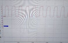
Вот по вашему предположение результат. Синий - это 3 пин. Красный 4 пин.А почему 3 пин а не 4? 3 пин измеряет температуру а 4 как раз таки воздушную массу
Посмотрите на оригинальную схему приведенную выше!А почему 3 пин а не 4? 3 пин измеряет температуру а 4 как раз таки воздушную массу
Hot film air mass meter DDE7, N47
The hot film air mass meter measures the mass of fresh air drawn in by the engine. The intake air temperature sensor is also integrated in the mass air flow meter.
The air mass serves as a measured variable in the DDE control unit for the following functions:
- Exhaust-gas recirculation - Calculating the limit quantity Function of mass air flow meter
Power supply and signals
The mass air flow meter is supplied with power and earth as follows:
The hot film air mass meter returns the air mass value via the signal T_HFM to the DDE control unit.
- The supply voltage of 12 V is furnished by Terminal 87 (signal name U_HR or 15N).
- The DDE control unit supplies the hot film air mass meter with an earth (signal name M_HFM). .
N47 only: The hot film air mass meter is earthed by the DDE control unit.
Note: Only if the DDE control unit detects an engine speed of more than 50 rpm is the earth contact of the HFM enabled. With the engine at a standstill and Terminal 15 On, the HFM is not connected to earth, which means that in this state it does not issue any signals!
This function is intended to prevent oil and contaminant residue from burning into the sensor element of the hot film air mass meter whenever Terminal 15 is hot.
The signal is a square wave signal with an amplitude of 5 V and frequency between 1.2 and -14 kHz. This frequency corresponds to a period duration of 0.8 - -0.07 ms.
The Digital Diesel Electronics control unit uses the frequency of this signal to calculate the air mass value with the unit mg/stroke.
Fault handling
Faults in the component hot film air mass meter result in one or more fault reactions:
- Exhaust-gas recirculation is deactivated - Deactivation of charging pressure control - Volume limitation - Output of a substitute value dependent on engine speed Function of the intake air temperature sensor
The intake air temperature sensor measures the temperature of the fresh air that is taken in by the engine.
Power supply and signals
The DDE control unit supplies the intake air temperature sensor with voltage and earth as follows:
The power supply output on the DDE can be activated.
The ground connection is across the cable M_HFM.
The intake air temperature sensor returns the intake air temperature via signal T_TANS to the DDE control unit.
The signal is a square-wave signal with an amplitude of 5 V and frequency of around 19 Hz. This frequency corresponds to a period duration of 53 ms.
The DDE control unit uses the pulse duty factor of this signal to calculate the intake-air temperature with the unit °C. The pulse duty factor can lie between 10 and 90 .
Fault handling
Faults in the component intake air temperature sensor result in one or more fault reactions:
- Exhaust-gas recirculation is deactivated - Deactivation of charging pressure control - Volume limitation - Output of a substitute value dependent on engine speed
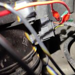
По-моему вы ошиблись с распиновкойПосмотрите на оригинальную схему приведенную выше!
Pin4 - управляемый минус расходомера через DDE
Pin3 - частотный выход ДТВВ
Pin2 - частотный выход сигнала расхода воздуха
Выкладка для страждущих о работе расходомера на двигателе N47
Посмотрите на оригинальную схему приведенную выше!
Pin4 - управляемый минус расходомера через DDE
Pin3 - частотный выход ДТВВ
Pin2 - частотный выход сигнала расхода воздуха
Выкладка для страждущих о работе расходомера на двигателе N47

Хорошо, вечером посмотрю. Но как это связано с дмрв? По какой то причине большинство считает, что это подсос воздуха. Мотор проверялся дымогенератором, протечек нет.Посмотрите нет ли люфтов на тягах актуатора турбины или чтото подключили что програмно отшито.
Подача массы осуществляется по проводу M_HFM.
Датчик температуры всасываемого воздуха с помощью сигнала T_TANS
Расходомер воздуха передает с помощью сигнала T_HFM
Соответственно получается что вы немного неправильно прочитали
Из за этого раз датчик показывает "-50", то дмрв начинает превышать разход воздуха.
Ваша мысль понятна! Спасибо!На схему расходомера внимательно посмотрите!
Кто где ошибся покажет результат результат диагностики и конечного ремонта.
Вы не ответили каким инструментом считываете показания ДТВВ?
В алгоритме работы DDE7 нет такой зависимости :"обрыв ДТВВ - превысить расход воздуха".
Измеренная масса воздуха это величина напрямую зависящая от реального количества воздуха во впускной системе и в математику, дальнейших расчетов максимального количества топлива, "обрыв ДТВВ" не вмешивается.
Бывает же! Блин, всё страшнее и страшнее становится. Как теперь по ночам то спать? Я и так все алгоритмы в голове прокручиваю.Было недавно Пежо 2019г 1.5 тди с ошибками по расходомеру,а оказалось цепь распредвальная гуляла,фазы не совпадали.???